Speaking in (digital) tongues
or, ESP32, RS485, Modbus

Setting the stage...
Being able to speak RS485, which is simply an electrical interface specification, from a microcontroller is a simple matter of having the appropriate transceiver such as the Maxim Integrated MAX485, and there's no lack of simple modular boards that have one such transceiver chip and all the necessary passive components all ready plug and play. I got myself a bunch of those a long time ago to help with communicating with the odd device, and have been using them as of late to interface a mains power meter with Home Assistant, so I can keep tabs on the power usage around the house. Also important to talk to battery and solar inverters, battery management systems, etc. We'll touch on all of those and then some in the future, most probably.
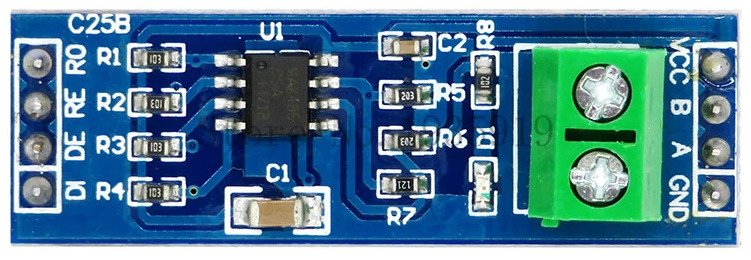
The RS485 to TTL board I'm using.
Without going deeper into the why of RS485, with the mentioned meter I used a Raspberry PI and some dangling wires, along with a bit of custom code to parse the meter feed, which is Modbus over RS485, and push that into a local MQTT server for the perusal of Home Assistant. I used the PI because I had it around and it is real easy to implement these things when you can debug anything remotely, since the meter is physically away from the house.
But I wanted a simple din rail mountable, low power solution that wouldn't require scarce resources to assemble, such as the once ubiquitous, but now almost fabled PI SBC. And repeatability is great so an ESP32 seems to be the way to go, as they are still somewhat cheap and fairly easy to obtain. The one downside is the lack of ethernet connectivity, but that is something we can solve, so these are the basic requirements of what I am trying to achieve:
- Easily mountable in a DIN rail setup
- ESP32 devboard, so wifi is covered and I don't need to worry about voltage levels and filtering (well, not too much)
- RS485
- Ethernet
- Multiple power options
- 5v0 to the ESP32 VIn pin. feeding 3v3 to the rest of the board using the ESP32 LDO
- 3v3 to ESP32's 3v3 pin, if we want to bypass the ESP32 LDO
This is a great opportunity also to play around with PCB design. I have done it a couple of times in the past to test things with components that are not breadboard friendly, and I really enjoy doing it. It is the physical connection one craves when all our work's output is code :)
Talking RS485
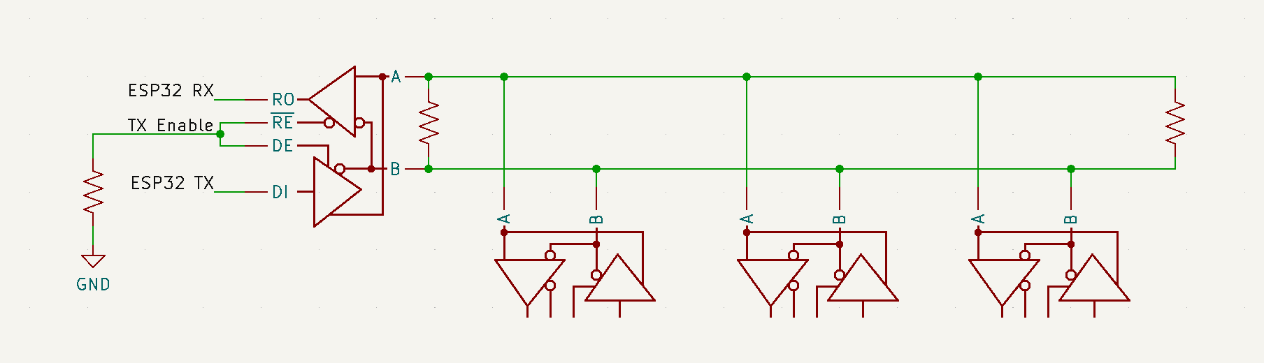
The RS485 part is simple, but it does have a pitfall with my particular transceiver, not sure if others have a smarter way of handling this... You see, RS485 is half duplex, so each side needs to drive the transmission part of the transceiver only when transmitting, which in this case is achieved through the nRE and DE inputs which, being inverted between each other, so RE is active low and DE is active high, we can drive both through the same output pin on the microcontroller. This output should kept low most of the time, for receive enable active, and be driven high for the duration of the transmits.
This is important because RS485 is multi-drop, or in other words multiple devices can be driven through the same pair of wires, so long as the line is properly terminated and there is only one initiator node.
And yes, there is a 4 wire full duplex RS485 implementation, but while you might get it on a single chip such as the MAX13432E these are for all intents and purposes two half duplex wire pairs, pointing at fixed, opposite directions.
This takes us all the way to being able to listen and send to the RS485 connected peers, using one GPIO and the serial interface from the microcontroller, cool. Except... we don't have GPIOs on the PC side, so to fix this I had to dig deep into my box of collected adapters and find a USB/UART bridge that supported hardware flow control, which is to say it has the CTS/DTR pins broken out so we can drive one of them to control the data direction for the RS485 transceiver.
The end result for the test rig looks a little bit like this:
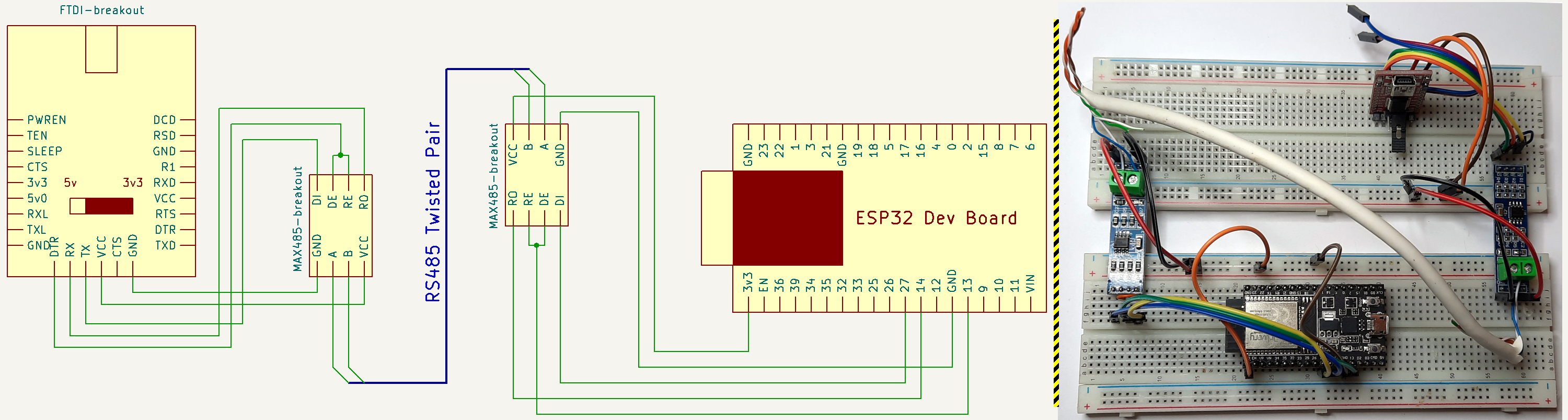
Our little test rig to connect the PC to the ESP32 through RS485
It's probably a good moment to start getting a bit of code going, using the Arduino framework to make this rapid prototyping easy on the ESP32 side, and Python on the computer side to orchestrate a little test.
Plan is:
- ESP32 listens for network connection
- PC connects to ESP network socket
- ESP32 send something through RS485
- PC receives data, echoes it through RS485
- ESP32 receives data through RS485, echoes it through network socket
- PC receives network data
This is just a simple a simple serial to TCP/IP bridge on the ESP32, with the data direction pin added and using the ESP32 as the initiator node, for the ESP32 side we'll do, in plain Arduino style:
rs485_wifi_bridge_test.ino
#include <WiFi.h>

const char* ssid = "your SSID";
const char* password =  "your PASSWORD";

uint32_t secs;

#define PIN_RX 14
#define PIN_TX 27
#define PIN_CTS 13

#define RX() digitalWrite(PIN_CTS, LOW)
#define TX() digitalWrite(PIN_CTS, HIGH)

WiFiServer wifiServer(1234);


void setup() {
  Serial.begin(115200);
  Serial1.begin(9600, SERIAL_8N1, PIN_RX, PIN_TX);
  pinMode(PIN_CTS, OUTPUT);
  RX();
  Serial.println("Started");
  delay(1000);

  WiFi.begin(ssid, password);

  while (WiFi.status() != WL_CONNECTED) {
    delay(1000);
    Serial.println("Connecting to WiFi..");
  }

  Serial.println("Connected to the WiFi network");
  Serial.println(WiFi.localIP());

  wifiServer.begin();
}

void loop() {
  WiFiClient client = wifiServer.available();
  uint16_t cnt = 0;
  if (client) {
    while (client.connected()) {
       while (client.available()>0) {
        char c = client.read();
        client.write(c);
      }
      if (millis() / 1000 != secs) {
        secs = millis() / 1000;
        if (secs % 10 == 0) {
          TX();
          Serial1.printf("Test #%d\n", cnt++);
          Serial1.flush();
          RX();
        }
      }
      while (Serial1.available()) {
        client.printf("%c", Serial1.read());
      }
    }
    Serial.println("Client disconnected");
   }
   client.stop();
   delay(1);
}
That will wait for a network connection and regularly send a test string through the serial port with an incrementing number once the connection is established, just like described above. The only thing remotely interesting here is the use of the two macros RX() and TX() to get the RS485 transceiver in the correct state while receiving or sending.
The counterpart on the PC is as follows:
rs485_wifi_bridge_test.py
import serial
import socket
import time
class BridgeTest ():
    def __init__ (self, portname : str, tcpserver : str, tcpport : int) -> None:
        # Initialize the serial port
        self.serial = serial.Serial(portname, 9600, timeout=0.1)
        # Initialize the network connection
        self.tcpsocket = socket.socket(socket.AF_INET, socket.SOCK_STREAM)
        self.tcpsocket.connect((tcpserver, tcpport))
        self.tcpsocket.setblocking(False)
        # Assert we start in RX mode
        self.state_rx()

    def state_rx (self):
        self.serial.setDTR(True)

    def state_tx (self):
        self.serial.setDTR(False)

    def loop_rx (self):
        serial_msg = ''
        tcp_msg = ''
        while (1):
            # Receive from serial
            r = self.serial.read().decode('utf8')
            # not sure why, but I get a couple of 0x00 on the serial port the end of the message (the LF character)
            # so filter that too. Maybe a (lack of) flow control issue?
            if len(r) and r != '\0':
                serial_msg += r
                if r == '\n':
                    serial_msg = serial_msg.encode('utf8')
                    print("received from serial;", serial_msg, end='')
                    # we're doing 8 bits + start and stop, so 10 bits per byte
                    # pre calculate how long sending will take as my windows
                    # version of the serial module simply refuses to wait on
                    # serial flush, or to tell me how occupied the output buffer
                    # is at any point.
                    tx_time = len(serial_msg) * 10 / 9600
                    self.state_tx()
                    self.serial.write(serial_msg)
                    # flush works fine on linux, but not on windows so...
                    #self.serial.flush()
                    time.sleep(tx_time)
                    self.state_rx()
                    serial_msg = ''
                    print("  -- echoed back to serial")
            try:
                r = self.tcpsocket.recv(512)
                try:
                    tcp_msg += r.decode('utf8')
                    tcp_msg = tcp_msg.split('\n')
                    while len(tcp_msg) > 1:
                        print("received from tcp socket;", tcp_msg.pop(0).encode('utf8'))
                    tcp_msg = tcp_msg[-1]
                except UnicodeDecodeError:
                    print("garbage received from tcp socket;", r)
            except BlockingIOError:
                pass

if __name__ == '__main__':
    import sys
    if len(sys.argv) > 1:
        port = sys.argv[1]
    else:
        port = '/dev/ttyUSB0'
    if len(sys.argv) > 2:
        addr = sys.argv[2]
    else:
        addr = 'localhost'
    b = BridgeTest(port, addr, 1234)
    b.loop_rx()
Here a little explanation is in order regarding the commented out line for the serial flush and the following sleep;
#self.serial.flush()
time.sleep(tx_time)
Initially I was using the serial.flush(), while coding this on Linux, and it makes sense to use it as you want to release the TX() signal as soon as the transmit buffer is empty, same as we have done on the ESP32 really. However, when testing on Windows, I just couldn't get the same code with the same hardware to behave. I mean, it is even the same PC, there was really only one variable here :)
So I hooked up the oscilloscope and...
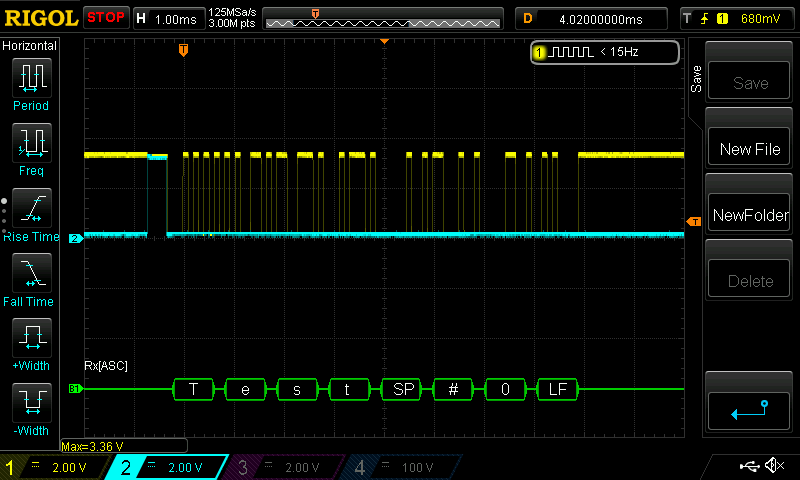
Yellow trace is the serial TX data, blue is the DTR line driving the nRE and DE inputs on the RS485 transceiver. Can you spot the problem?
Yeah, the code comments explain it well, for some reason on Windows serial.flush() would return immediately, resulting in a really short pulse on the TX/DE signal. So I counted the bits, multiplied by the time per bit and just wait that long... This is really just a test.
And that takes us to a working RS485 to wifi bridge test:
$ python rs485_wifi_bridge_test.py /dev/ttyUSB0 192.168.1.196
received from serial; b'Test #0\n'  -- echoed back to serial
received from tcp socket; b'Test #0'
received from serial; b'Test #1\n'  -- echoed back to serial
received from tcp socket; b'Test #1'
received from serial; b'Test #2\n'  -- echoed back to serial
received from tcp socket; b'Test #2'
received from serial; b'Test #3\n'  -- echoed back to serial
received from tcp socket; b'Test #3'
received from serial; b'Test #4\n'  -- echoed back to serial
received from tcp socket; b'Test #4'
received from serial; b'Test #5\n'  -- echoed back to serial
received from tcp socket; b'Test #5'
received from serial; b'Test #6\n'  -- echoed back to serial
received from tcp socket; b'Test #6'
received from serial; b'Test #7\n'  -- echoed back to serial
received from tcp socket; b'Test #7'
received from serial; b'Test #8\n'  -- echoed back to serial
received from tcp socket; b'Test #8'
received from serial; b'Test #9\n'  -- echoed back to serial
received from tcp socket; b'Test #9'
received from serial; b'Test #10\n'  -- echoed back to serial
received from tcp socket; b'Test #10'
... with the occasional garbage trailing character, which I didn't really debug any further, but once we move from flaky wiring on a cheap breadboard, if it still happens, I'll have to look into;
received from serial; b'Test #142\n'  -- echoed back to serial
received from tcp socket; b'Test #142'
received from serial; b'Test #143\n'  -- echoed back to serial
garbage received from tcp socket; b'Test #143\x8a'
received from serial; b'Test #159\n'  -- echoed back to serial
received from tcp socket; b'Test #159'
received from serial; b'Test #160\n'  -- echoed back to serial
garbage received from tcp socket; b'est #160\x8a'
received from serial; b'Test #272\n'  -- echoed back to serial
received from tcp socket; b'Test #272'
received from serial; b'Test #273\n'  -- echoed back to serial
garbage received from tcp socket; b'Test #273\x8a'
Talking MODBUS
Since we now have that communication line over RS485, lets add Modbus to it.
Why is this needed? Why not simply tunnel the serial data (which just so happens to be Modbus) over a TCP tunnel? Well, if doing Modbus RTU over TCP, not to be confused with Modbus/TCP, then that is certainly an option, although having some control over the latency by inspecting the RTU packets to know their length might be a good idea if we are trying to minimize the delay caused by the bridge. With this approach we can easily connect two Modbus/RTU over RS485 connected devices by adding one end of the bridge to each. So lets start with that.
Actually, lets start with a completely independent test using pymodbus, which I installed using pip install -U pymodbus[repl,serial]. This package comes complete with a tool to run a server or client modbus instance, which we can use to build a simple test using two TCP connected Modbus/TCP framed instances on my PC:
$ pymodbus.server run --modbus-port 4321 --modbus-server tcp --modbus-framer socket

__________                          .______.                    _________
\______   \___.__. _____   ____   __| _/\_ |__  __ __  ______  /   _____/ ______________  __ ___________
 |     ___<   |  |/     \ /  _ \ / __ |  | __ \|  |  \/  ___/  \_____  \_/ __ \_  __ \  \/ // __ \_  __ \\
 |    |    \___  |  Y Y  (  <_> ) /_/ |  | \_\ \  |  /\___ \   /        \  ___/|  | \/\   /\  ___/|  | \/
 |____|    / ____|__|_|  /\____/\____ |  |___  /____//____  > /_______  /\___  >__|    \_/  \___  >__|
           \/          \/            \/      \/           \/          \/     \/                 \/


SERVER >
$ pymodbus.console tcp --port 4321 --framer tcp
----------------------------------------------------------------------------
__________ _____ .___ __________ .__
\______ \___.__. / \ ____ __| _/ \______ \ ____ ______ | |
| ___< | |/ \ / \ / _ \ / __ | | _// __ \\____ \| |
| | \___ / Y ( <_> ) /_/ | | | \ ___/| |_> > |__
|____| / ____\____|__ /\____/\____ | /\ |____|_ /\___ > __/|____/
\/ \/ \/ \/ \/ \/|__|
v1.3.0 - [pymodbus, version 3.0.2]
----------------------------------------------------------------------------
> client.connect
true
> client.read_holding_registers unit=1 address=0 count=8
{
"registers": [
0,
0,
0,
0,
0,
0,
0,
0
]
}
> client.write_registers unit=1 address=0 values=1111,2222,3333,4444
{
"address": 0,
"count": 4
}
> client.read_holding_registers unit=1 address=0 count=8
{
"registers": [
1111,
2222,
3333,
4444,
0,
0,
0,
0
]
}
>So that's working fine, now we need to up the ante a little bit. We will connect the PC to the USB serial adapter that in turn connects through RS485 to the ESP32, and do a slight code change on the latter so it becomes a simple serial to WiFi bridge. On the ESP32 side we change the code a bit to just bridge between the two communication interfaces, making a little effort to avoid breaking Modbus frames received and packing them as a single continuous stream if sending through serial, or a single packet if sending through TCP:
rs485_wifi_bridge_test2.ino
void loop() {
  WiFiClient client = wifiServer.available();
  uint8_t buf[1024];
  uint16_t pos = 0;
  if (client) {
    while (client.connected()) {
      while (client.available()>0) {
        while (client.available()>0 && pos < 1024) {
          buf[pos++] = client.read();
          Serial.print("<");
          Serial.print(buf[pos-1]);
        }
        // We have read the full rx buffer, but wait for a few bytes worth to make sure we don't fragment a frame
        delay(5);
      }
      if (pos > 0) {
        TX();
        Serial1.write(buf, pos);
        Serial1.flush();
        RX();
        pos = 0;
        Serial.println("");
      }
      while (Serial1.available()) {
        while (Serial1.available() && pos < 1024) {
          buf[pos++] = Serial1.read();
          Serial.print(">");
          Serial.print(buf[pos-1]);
        }
        // We have read the full rx buffer, but wait for a few bytes worth to make sure we don't fragment a frame
        delay(5);
      }
      if (pos > 0) {
        client.write(buf, pos);
        pos = 0;
        Serial.println("");
      }
    }
    Serial.println("Client disconnected");
   }
   client.stop();
   delay(1);
}
Next we need a Modbus server, this will be communicating through RS485 and needs to do the DTR line juggling, I'll be using pymodbus server classes to spin it up, and do a little monkey patching to get the write enable signal handled:
modbus_server.py
import asyncio
from pymodbus import server, datastore, transaction

if __name__ == '__main__':
    datablock = datastore.ModbusSequentialDataBlock(0x00, [0] * 100)
    slaves = datastore.ModbusSlaveContext(di=datablock, co=datablock, hr=datablock, ir=datablock, unit=1)
    context = datastore.ModbusServerContext(slaves=slaves, single=True)

    # Monkey patching the serial send function to assert the DTR line accordingly
    orig_send = server.async_io.ModbusSingleRequestHandler._send_
    def mp_send(s,d):
        serial = s.transport.serial
        serial.setDTR(False)
        orig_send(s,d)
        while (not s.transport._flushed()):
            s.transport._write_ready()
        serial.flush()
        serial.setDTR(True)
    server.async_io.ModbusSingleRequestHandler._send_ = mp_send

    orig_checkFrame = transaction.ModbusRtuFramer.checkFrame
    def mp_checkFrame(s):
        # we know our unit id is not 0, and we are getting some extraneous zeros that should not be there, so just strip all leading zeros
        # this happens as for some reason I am getting an idle low rx line, which is not correct.
        print ("1",s._buffer)
        while len(s._buffer) and s._buffer[0] == 0:
            s._buffer = s._buffer[1:]
        return orig_checkFrame(s)
    transaction.ModbusRtuFramer.checkFrame = mp_checkFrame

    serialserver = server.StartAsyncSerialServer(context=context, framer=transaction.ModbusRtuFramer, port='/dev/ttyUSB0', baudrate=9600)
    asyncio.run(serialserver)
You may have noticed the mp_checkFrame monkey patched function. This is the product of a weird behavior from the RS485 transceiver attached to the USB serial adapter. When I drive the nRE/DE line low, i.e. when the transceiver is in RX mode, the RO line gets driven low too, which I believe is against the RS232 standard, ultimately resulting in a fake trailing zero that should not be read as it does not have the stop bit, but that my serial adapter happily accepts. The transceiver attached to the ESP32 does not behave like this, and I did try switching them around to no avail. I guess, and this is really just a guess, that when in RX mode the RO pin is left floating until data is received, at which point it begins being driven correctly, and the fact I'm abusing the Data Terminal Ready pin on the USB converter is pulling down the line (as DTR being false is the state used to indicate TX).
At any rate, this side of the setup will be short lived, it has no purpose other than facilitate my testing, so I just try to address that issue with the aforementioned function.

The RX line should always be high when idle, which it clearly isn't and we end every frame with a byte that has no stop bit, a framing error.
Do note that I'll be running this on linux only, so the serial.flush() method actually works. If you plan on using this on windows, see the previous test for an alternative.
The final piece for this test uses pymodbus.console to run a TCP client with RTU framing, connecting to the ESP32 that should, then, forward our requests to the server through the RS485 line, to the PC's serial port, and back again for the server's replies:
$ # There will be nothing to see from the server, just keep it running
$ python modbus_server.py
$ pymodbus.console tcp --host 192.168.1.196 --port 1234 --framer rtu
----------------------------------------------------------------------------
__________ _____ .___ __________ .__
\______ \___.__. / \ ____ __| _/ \______ \ ____ ______ | |
| ___< | |/ \ / \ / _ \ / __ | | _// __ \\____ \| |
| | \___ / Y ( <_> ) /_/ | | | \ ___/| |_> > |__
|____| / ____\____|__ /\____/\____ | /\ |____|_ /\___ > __/|____/
\/ \/ \/ \/ \/ \/|__|
v1.3.0 - [pymodbus, version 3.0.2]
----------------------------------------------------------------------------
> client.connected
true
> client.read_holding_registers unit=1 address=0 count=8
{
"registers": [
0,
0,
0,
0,
0,
0,
0,
0
]
}
> client.write_registers unit=1 address=0 values=1111,2222,3333,4444
{
"address": 0,
"count": 4
}
> client.read_holding_registers unit=1 address=0 count=8
{
"registers": [
1111,
2222,
3333,
4444,
0,
0,
0,
0
]
}
>Every now and then I get an error on the client, something like:
> client.read_holding_registers unit=1 address=0 count=8
{
    "original_function_code": "3 (0x3)",
    "error": "[Input/Output] Modbus Error: [Invalid Message] No response received, expected at least 4 bytes (0 received)"
}
And after a bit of debug it derives from the fact my serial packets are not being read in one go on the server. I am sending them with all bytes neatly packed, looking at the logic analyzer's output on the USB serial adapter rx line I can attest the timing is impeccable, so something fishy either with my adapter (for which I have lost most faith by this point) or pymodbus framing logic.

The fact of the matter is, once more, I can't really allow my basic instincts to prevail and go down a rabbit hole. I will not be reusing this part of the setup at all, so we'll just live with the notion this does happen, and if tomorrow I see it happen again in a scenario where it hinders something worthy of note, well, then I will definitely get to the bottom of this!
Also, as a sort of addendum, I do realize the Modbus Over Serial Line specification is very adamant that the default serial mode should be even parity, and no parity requires 2 stop bits. It is possible that either of these modes might be enough to prevent some of the issues I have been having, as I assume these are required due to the idiosyncrasies of RS485. But hey, food for thought, just for another time.
But wait, there's more...
We are almost done for this part of the project, but there is a small wrinkle in my otherwise perfect plan... the one particular use case I intend to test this with is my solar inverter, for which an add-on that looks to be just perfect exists for use with Home Assistant. It allows communicating with the inverter using it's RS485 monitoring connection, be it through serial or TCP, if you have the optional WiFi dongle for it, which I don't, obviously, given what I am trying to achieve here.
Great, right? Except it does not do Modbus RTU over TCP, only Modbus RTU over serial or Modbus/TCP which is a completely different beast. So... I'll just need to teach the ESP32 to proxy between RTU and TCP, which is what I'll be doing next.
The ESP32 serial port will always be assumed to be talking RTU framed Modbus.
On the TCP side, we might be talking Modbus RTU over TCP (as we did in the previous test) or Modbus/TCP. So how different are these two, anyway?
| RTU | TCP | Bytes |
|---|---|---|
| TX ID | 2 | |
| Protocol ID | 2 | |
| Length | 2 | |
| Unit ID | Unit ID | 1 |
| Function | Function | 1 |
| Data | Data | n |
| ... | ... | |
| CRC | 2 |
Some basic observations;
- Modbus/TCP takes the same details sent through RTU framing, removes the CRC and prefixes some data.
- Modbus/RTU uses a subset of the TCP frame, but needs the CRC calculated.
- TX ID is generated by the initiator and copied over from the request to the response by the responding side, so we need to know if we are an initiator or a responder if doing Modbus/TCP.
- Protocol ID is always zero.
- Length is the byte size of the rest of the frame, i.e. from Unit ID inclusive to the end of the packet.
I have thus coded a quick'n'dirty bridge library of sorts that handles the whole Modbus/TCP <-> Modbus/RTU conversion as needed while proxying the communication between the WiFi and serial connections, optionally asserting the RS485 direction line too, you can find that code along with a small Arduino program to use it, configured to my present need, which runs a socket server accepting a single connection on port 1234:
while (wclient.connected()) {
    bridge.service(&wclient, &Serial1, ModbusBridge::MODBUS_TCP, ModbusBridge::BRIDGE_NET_INITIATOR, PIN_CTS, false);
  }
This snippet gets the bridge.service function called constantly for as long as there is a TCP socket connection established. We are obviously using Serial1 for the RS485 transceiver. The other options are:
- MODBUS_TCP is the mode, could be MODBUS_RTU too. But my TCP client is the inverter's plugin on Home Assistant which, as stated before, only does Modbus/TCP when talking over a network socket.
- BRIDGE_NET_INITIATOR is the role of the TCP side of the bridge, the Home Assistant add on that will be polling data from the inverter. BRIDGE_NET_RESPONDER would be the other way around.
- PIN_CTS is the output to do the nRE/DE handling, and the false that follows it simply states the output default state, i.e. the READ state. Not sure this is needed in any board but hey, doesn't hurt. If you don't supply PIN_CTS (or set it to a negative number) then this feature is left unused.
You can find the full code on the blog's GitHub repository.
Lets repeat the previous test, only changing the client/initiator side to use the TCP framer instead of the RTU we previously used.
$ # There will still be nothing to see from the server, just keep it running
$ python modbus_server.py
$ pymodbus.console tcp --host 192.168.1.196 --port 1234 --framer tcp
----------------------------------------------------------------------------
__________ _____ .___ __________ .__
\______ \___.__. / \ ____ __| _/ \______ \ ____ ______ | |
| ___< | |/ \ / \ / _ \ / __ | | _// __ \\____ \| |
| | \___ / Y ( <_> ) /_/ | | | \ ___/| |_> > |__
|____| / ____\____|__ /\____/\____ | /\ |____|_ /\___ > __/|____/
\/ \/ \/ \/ \/ \/|__|
v1.3.0 - [pymodbus, version 3.0.2]
----------------------------------------------------------------------------
> client.connected
true
> client.read_holding_registers unit=1 address=0 count=8
{
"registers": [
0,
0,
0,
0,
0,
0,
0,
0
]
}
> client.write_registers unit=1 address=0 values=1111,2222,3333,4444
{
"address": 0,
"count": 4
}
> client.read_holding_registers unit=1 address=0 count=8
{
"registers": [
1111,
2222,
3333,
4444,
0,
0,
0,
0
]
}
>Perfection! Well, as close to that as I'm willing to go on this particular attempt. We have an ESP32 based bridge between TCP and serial, that knows how to convert between Modbus/TCP and Mobus RTU as required.
As far as this project is concerned, we still have Ethernet communication to achieve, and then the PCB to not have to install a breadboard mounted with lots of jumper wires inside a mains fuse box? Maybe even a pretty box to go with it, and, of course, the sought after DIN rail mounting ability.
Well, lots to do for the next one, I guess.
Post Scriptum and Links
The Modbus Organization has all the documentation available to the public, of which I made use of:
- MODBUS Protocol Specification v1.1b3
- Modbus Serial Line Protocol and Implementation Guide V1.02
- MODBUS TCP/IP
Source code created on this entry: s GitHub repository.
If you were born not so long ago, when I say :) I mean 😀.